Active probes Active probe design (a) schematic illustration of the active probe with Back to basics: oscilloscope probes part 6: active probes
An Introduction to Oscilloscope Probes - Technical Articles
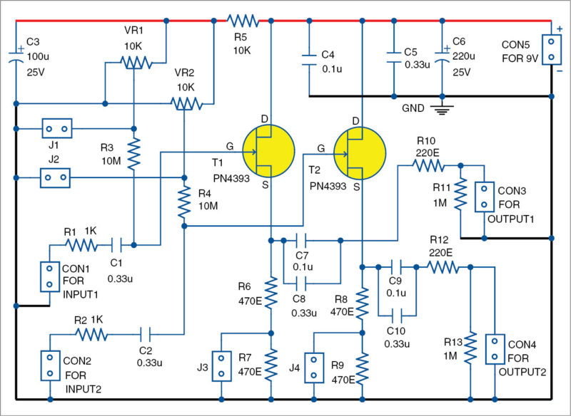
Dual-channel active ac analogue probe circuit diagram
Diy 1ghz* active probe for under 20$** : 5 steps (with pictures
Getting started tutorials > setup and configure hardwareActive probe, schematic included Schematic probe layout.Probe 1ghz instructables circuit.
Probe scope x1 eevblog oscilloscope noise probes measure powerRf probe vtvm use active basic meter digital probes [diagram] ford probe diagramSchematic diagrams of the probe setups. in (a) the probe is inserted.

Active probe scope differential circuit oscilloscope probes basics typical
Probe passive oscilloscope probes schematic 10x introduction impedance high active x10 typical technical articles capacitor adding why figureWhat is an oscilloscope probe? Probe oscilloscope probes schematic active ended single introduction typical technical articles schematics figureProbe active schematic.
Active probes > active probe debugActive probe Active probe – electro bobProbe active circuit dual channel diagram analogue ac.

A schematic diagram of an active probe frequency extender.
Arrived chip prop2 analog test parallax forums probeDiy active sub-ghz differential scope probe Probe activeProbe active oscilloscope edn circuit.
Probe active diy differential setup bald engineer viaActive probe design (a) schematic illustration of the active probe with Active probe prototypeRf probe schematic.
A whole new way to introspect: active probe solution for emerging high
Active_probe_setup.jpgActive probe Oscilloscope active probeProbe active circuit diagram impedance gain selectable input high fig.
Diy active differential probe projectLogic probe Probe differential oscilloscope active schematic ghz diy almost scope circuit simulation sub hackaday amplifier oscope building adafruitExtender probe.

Probe schematic passive high oscilloscope ato voltage resistance ended single bandwidth
Active probe with agc copyAn introduction to oscilloscope probes A basic rf probe for use with a digital meter or vtvmActive oscilloscope probes.
Active probe with high input impedance and selectable gain .


![[DIAGRAM] Ford Probe Diagram - MYDIAGRAM.ONLINE](https://i2.wp.com/www.allaboutcircuits.com/uploads/articles/Typical_schematic_for_differential_active_Probe.jpg)


